Hardware overview and plotting the temperature curves of this heating table to see if it can be used for SMD reflow soldering
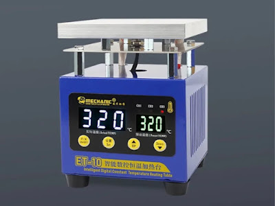
I've been looking recently to buy a hot plate for SMD work. I didn't like the big 20 by 20 cm ones since I will not be doing such big PCBs. I also didn't like the Miniware 3 by 3 cm hot plate, because this is too small for my needs (and rather expensive). I decided to buy a 10 by 10 cm heating table, and Mechanic ET-10 caught my eye. More specifically I liked the hot plate itself, which is a 10 x 10 x 1.2 cm thick block of aluminum. It has two holes drilled through the back where two heating elements are inserted.
I eventually bought it and from the outside it seems a solid design. However, just as I turned it on and set its temperature, I heard a relay clicking inside. Well, using a relay for an "Intelligent Digital Constant Temperature" is something that does not look very good. The aluminum heating block has an important volume, therefore a high heat inertia. The best way to get it to a constant temperature is to use PID (proportional-integral-derivative) controller. And I don't think this is how its controller works.
 |
| Mechanic ET-10 hot plate |
Operating instructions
Let's start with the operating instructions. There are three "channels" which represent temperature presets. The odd thing is that each has to have a higher temperature preset than the previous (CH1 < CH2 < CH3).
You use the ON/OFF button to turn it on, then using SET you select one of the presets (channels). While the channel LED is blinking you can adjust preset temperature with the UP/DOWN buttons. After the channel LED has stopped blinking the preset temperature is stored and the heater turns on to reach it.
You will hear the relay clicking. When it is very close to preset temperature, you hear the relay switching off and on a few times. Unfortunately, the plate temperature continues to increase a bit above the preset. And the big display (which is for actual temperature) will not show you more than the preset value. If you turn it off and back on, you will see the real temperature on this display.
There is a hidden menu. Press and hold SET for at least 3 seconds and when all channel LEDs turn off, you will see P0 on the small display. I assume P0 stands for "parameter 0" and it can be set from 1 to 30 (default 2). Use UP/DOWN buttons to select between P0 and P1. The latter is default 0 and can be set from -20 to +20. It is used to calibrate the actual temperature offset. When P0 or P1 is displayed, press SET again to see parameter value and use UP/DOWN to change it. Press SET to store. I'm still trying to figure P0 meaning.
Temperature controller
On the bottom face of the aluminum plate there is a screw thermocouple. I eventually opened the case to take a closer look at the temperature controller (it can be opened by removing bottom lid). Easier said than done since the controller PCB (which also contains the 7 segment displays) is screwed on standoffs attached to the front face. What kind of tools did they use to put those screws there at a 90 degrees angle from below, I have no idea. It was not such a big surprise to see that, although there are 4 screw holes on PCB with corresponding standoffs, only three screws were used.
I had to use an angled bit driver and a flexible shaft screwdriver to get those screws out. And putting them back was even harder... Anyway I succeeded. Unfortunately, the controller is not what I would expect.
 |
| Mechanic ET-10 controller top PCB |
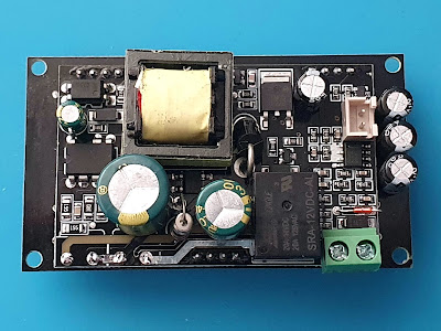
There are two stacked PCBs. The top one (MCN-G1009 V1.1) contains the pushbuttons, the LED displays and probably a microcontroller. The bottom one is attached to it using three 4-pin headers and this one contains the switching power supply, relay and thermocouple amplifier.
Overall, the only thing I don't like about the top PCB is the lack of proper holes which would connect the ground to the metal chassis. On the bottom PCB there are also some things I don't like. High voltage and low voltage tracks are mixed on the PCB and I don't like this. Also the space between the two stacked PCBs is quite low and some through-hole part terminals come very close from one board to the other (some are even from the high voltage side of the power supply).
 |
| Mechanic ET-10 controller bottom PCB |
The relay is SRA-12VDC-AL manufactured by Songle, and there is a problem with it: nowhere in its specifications is mentioned that it is suitable for 230 VAC... Datasheet clearly states maximum switching voltage of 125 VAC. They shouldn't have used a relay in the first place, yet they did and it is not even a suitable one for the 220 V version of this product.
Moving further to the thermocouple amplifier, I noticed it is based on LM358, a common op-amp. Yes, it is possible to use a common op-amp such as the LM358 to amplify the signal from a thermocouple. However, there are some important considerations to keep in mind when doing so. The voltage output of a thermocouple is typically in the range of a few microvolts to a few millivolts, depending on the type of thermocouple and the temperature being measured. To amplify this small voltage, you will need to use an amplifier with a very high gain and a low noise level.
The LM358 is a general-purpose operational amplifier that is widely used in many different applications. However, it may not be the best choice for amplifying the signal from a thermocouple because it has a relatively low gain bandwidth product (GBW) and a relatively high noise level. There are other op-amps available that are better suited for amplifying small signals, such as those from a thermocouple.
Temperature curves
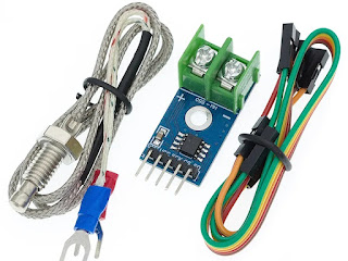
I got a thermocouple with MAX6675 driver and I will attempt to plot temperature curves for each of the three presets. I would never expected this to be so difficult. After all, they also use a thermocouple.
 |
| MAX6675 thermocouple module |
I wired the above to an Arduino board and made a contraption to keep the thermocouple tip in close contact with the plate. Besides the thermal coupling problem (the tip is rounded and the contact surface is reduced) I got some electrical issues: as soon as I touched the thermocouple to ET-10 (having both the hot plate and PC with Arduino grounded) all readings were zero. I can't really understand why since I even tried with my laptop, battery powered.
Yet, still with the thermal coupling problem in my mind, I decided to take the actual thermocouple out of that screw case. To my surprise, it is just crimped inside, without any thermal paste. So I put some thermal paste in the center of the plate and held the thermocouple in place there. And the reading error is now gone. I solved two issues at once.
As a side note, this is the exact type of thermocouple used by the plate. It is screwed on the bottom face and there is enough room to allow the thermocouple tip to move.
 |
| Thermocouple used to measure Mechanic ET-10 temperature |
And now, measuring temperatures and plotting curves is going to take way more than I expected. The big aluminum plate cools down very very slow. Anyway I'm using an ESP8266 WeMos D1 mini board to send time (number of seconds since start), analog pin readout and current temperature, comma separated. Data is logged using PuTTY connected to serial port.
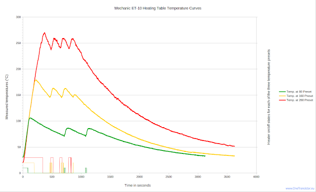
What is with the analog input of ESP8266? Well, I used a current transformer, rectified and filtered its output then sampled it with the ADC. In this way, I know when the heating table draws current (meaning the heater is on). I imported data in LibreOffice Calc and processed it. These are the results:
The thick lines show the measured temperatures for each of the three presets (80°C, 160°C and 260°C). The thin lines at the bottom display the state of the heater (on or off) with corresponding colors for each preset. Those lines end when the device was turned off. Notice the poor temperature stability of this "intelligent controller". You can also see that the big aluminum plate needs slightly more than an hour to cool down.
At this point, if you bought this for reflow soldering, you might be wondering it is even usable for this purpose. I took a common reflow profile and tried to fit it with the measurements I made.
The reflow profile is from ESP-12F product specifications by Ai-Thinker. I used WebPlotDigitizer to get graph data which was imported in Calc.
Ok, I would say the result is surprisingly, yes. There shouldn't be any major issue with the fact that ET-10 heats up slower than required. However, there is a problem with the very slow cool down. So, here are my recommendations, assuming the above reflow profile:
- Place your PCB on the heating table.
- Set Mechanic ET-10 temperature to 240°C (in this way the peak will easily get to 250°C).
- Wait for an average of 6 minutes. Visually inspect the reflow process during this time.
- Get a lift table with some heat resistant pad on it and put it next to the heating table.
- Carefully slide the hot PCB to the lift table. Be very patient since any sudden move will displace most, if not all parts on the PCB.
- Power off Mechanic ET-10.
This is a simple usage scenario which worked for me. However, you can attempt the next approach too:
- Place your PCB on the heating table.
- Set Mechanic ET-10 temperature to 160°C (i.e. use preset 2).
- Wait for 4 minutes.
- Switch to 240°C (i.e. use preset 3).
- Wait for 2 minutes.
- Move the PCB to the lift table and power off the heating table.
 |
| Mechanic ET-10 with lift table next to it |
Conclusion
Mechanic ET-10 is a general purpose heating table which caught my attention for SMD reflow use. Although it has a massive heated block of aluminum, this cannot fit the rapid cooling needed for reflow. With the non-PID relay temperature controller and the poorly fitted themocouple, Mechanic ET-10 fails when temperature precision and stability is required.


No comments :
Post a Comment
Please read the comments policy before publishing your comment.