Build this analog gas detector based on almost any MQ tin dioxide sensor with running, missed and real time alarm LED indicator
Nowadays people are using microcontrollers even for blinking an LED. And that is no problem, since they are cheap enough, have low power consumption and are easy to program. But there was a time when microcontrollers were expensive and hard to find. And even then, engineers were building working devices, just smart enough to do the job they were designed for. Let's try to build a "microcontroller-less" gas detector using one of the MQ sensors.
Gas sensors from MQ family are analog tin dioxide detectors which change their resistance in the presence of volatile compounds like gases or smoke. Except MQ-7 and MQ-9 which are designed for carbon monoxide detection and require alternating heater voltage, with analog output being read at the end of each heater voltage cycle, every other sensor may be used in the following circuit.
 |
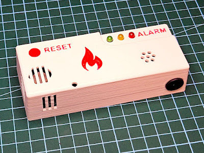
| Built analog gas detector with 3D printed enclosure |
Having a variable resistance, the most easy to build is a simple comparator which will trigger an alarm when voltage drop across sensor reaches a threshold. Yet, there are some issues. And we can build something better. At startup, while it is heating, sensor resistance will vary and can easily reach the alarm threshold. I don't want a detector which will trigger the alarm when powered on. The other feature I really want is an indication of a previous alarm. That is, if the sensor detected gas or smoke and there was no one around to hear the alarm, I want to find an indicator later on, even if gas or smoke is no longer present. And at last, most detectors come with an indicator which blinks every now and then to let you know it is powered. Sounds like a job for a microcontroller? Well, yes. But it doesn't mean I can't implement the features I want with discrete components and common ICs.
 |
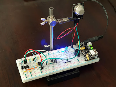
| Gas detector with MQ-2 module on breadboard |
In the above prototype I used an MQ-2 module and connected its DOUT output to the breadboard circuit. Later on I added the power on blinking LED. Let's have a look at the schematic. Note that only the top circuit is built on breadboard.
 |
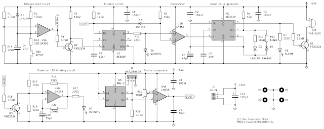
| Analog gas detector schematic |
It is not as complicated as it looks. Starting from the left, there is the delayed start circuit. Built around a half of a LM358 op-amp, used here as a comparator, R2 slowly charges C4. By the time it is fully charged, the voltage at its positive pin exceeds the output voltage of R1-R14 divider. Therefore U1A switches its output from high to low. D1 helps discharge the capacitor fast when power is removed. SW1 let's you quickly discharge the capacitor via R12. This is useful to deactivate the alarm for a short period of time. Speaking of time, the delay is dependent on R2 and C4 values. You can use higher values for more time.
When U1A output goes low, two things happen. The bistable circuit built around NE555 is no longer under reset, since Q2 is turned off and reset pin is pulled high by R3. Any low input on U3 threshold pin (where DOUT is connected) will trigger its output to high. This will stay high as long as the circuit is powered and reset is not active.
Q3 is the other transistor which gets turned off when U1A output switches to low. This allows the voltage divider R15-R19 to bias the non-inverting input of U4B, and it starts to oscillate at a frequency determined by R20 and C10. LED D7 starts blinking to indicate the circuit is powered on and running.
Back to the output of U3. If it is low (when under reset or no alarm), the inverting input of U1B is pulled up by R5, therefore its output is low, keeping U2 under reset. Assuming the sensor resistance reaches the alarm threshold and DOUT goes low, the inverting input of U1B can't go lower than 0.7 V (because of D2). Since the non-inverting input voltage level is still 0 V (with U3 under reset), U1B output can't go high.
Otherwise, if U3 is no longer under reset, when DOUT goes low it does two things: switches U3 output to high providing a voltage on the non-inverting input of U1B equal to D6 LED voltage drop and pulls the inverting input down to the voltage drop on D2 (which is less than LED voltage drop). U1B output goes high, thus enabling U2 which pulses the alarm LED and buzzer through Q1 driver. Width of pulses is determined by R10/R11 ratio and frequency by C5 capacitor.
I also included in the circuit the comparator used by MQ module. I don't plan using the module as long as I have an unused half of op-amp IC. I will remove the sensor from module board and put it on my own PCB.
Feel free to use higher value resistors for R13, R7 and R17. Those high brightness LEDs make my eyes hurt even though I used 330 ohms current limiting resistors (I couldn't even take a photo of the PCB while LEDs were on). Also, C4 and R2 values may be increased to delay the alarm enable long enough for the sensor resistance to settle down.
If you would like to use a different kind of sensor or module instead, there is J2 pin header. Do not place R21 on PCB and use the middle pin of the connector to feed any analog or digital signal directly to the comparator.
 |
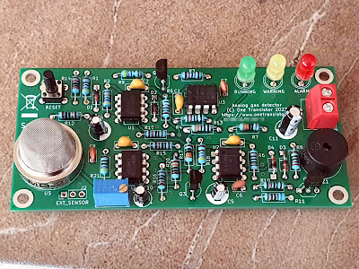
| Analog gas detector built on PCB |
This circuit must be powered from 5 V (±0.1) to match sensor heater specs. Due to this heater resistor, while the buzzer is on it draws about 200 mA, therefore a suitable power supply should be 5 V DC @ 0.3 A.
The only limitation of this circuit is the lack of temperature and humidity compensation. But this doesn't mean it can't be calibrated and used in an environment with rather constant temperature and humidity. Please keep in mind that tin dioxide sensors are not very accurate and this is a DIY design with potential flaws. Whenever you need such a detector, buy a professionally manufactured one.
Trimmer RV1 is used to adjust trigger point (sensitivity). Turn it clockwise to decrease sensitivity. Except MQ-7 and MQ-9 which require cycling heater voltage, every other sensor from MQ family is a direct replacement in this circuit. Use whatever suits your needs.
Finally, if you build this, when placing resistors on PCB, make sure not to switch R4 with R13. I did so, since the way I placed references doesn't make it very clear which is which. R4 is closer to the NE555 timer U3. I would probably make the time to upload a revised PCB design with RV1 rotated 180 degrees (in order to turn clockwise to increase sensitivity) and with better placement of R4/R13 references. For now, this is the archive I sent to a PCB manufacturer: mq_analog_gas_detector.zip (contains KiCad project with Gerber files).


No comments :
Post a Comment
Please read the comments policy before publishing your comment.