How to use MQ-7 and MQ-9 sensors to measure concentration of carbon monoxide. Sensors must be removed from existing module boards.
When shopping for electronics parts and modules, I oftentimes add to cart things I didn't plan to buy, since most suppliers offer free shipping when total order amount is above a threshold. This was the case with a module I bought recently, a carbon monoxide and LPG detector based on MQ-9 sensor. When I got the time to build a breadboard circuit to test it, I came across a problem. As with most modules and devices, I started with MQ-9 datasheet. And at first I did not quite understand what they were saying about high and low heater voltage.
And the internet is full of examples regarding such modules interfaced to Arduino. And almost everybody seems to be powering it from 5 V, while some even developed code with advanced calculations to get real ppm value from the sensor. Throughout reading of the datasheets of both MQ-7 and MQ-9 reveals a "detail" almost everybody seems to have missed. In this post I will show you the correct way of using MQ carbon monoxide sensors. Keep in mind that CO and LPG are dangerous gases and if you need a detector, you should always buy a professionally manufactured one which is also properly calibrated.
 |
| MQ-9 ready for testing |
MQ-7 is carbon monoxide specific. However, MQ-9 can detect both CO and LPG. So, how do you get the concentration of one or the other gas? Well, I found a possible answer at robu.in:
It makes detection by cycling high and low temperature and detects CO when low temperature (heated by 1.5V). The sensor’s conductivity is higher along with the gas concentration rising. When temperature rises (heated by 5.0V), it detects Methane, Propane, combustible gas, etc and cleans the other gases as it adsorbed under low temperature.
This makes it clear to me. The MQ-9 sensor heater should be powered from 5 V, then switched to 1.4 V. Readings should be made after a certain amount of time. In the same way, MQ-7 heater voltage should be cycled, and readings should be made only when heater is powered with low voltage (1.4 V). Sticking to MQ-9, which is what I have, the datasheet shows a graph and explains when readings should be made:
 |
| Heater voltage and output signal of MQ-9 sensor (from datasheet) |
It is rather simple: heater voltage is set to 5 V. After 60 seconds a reading is made, reflecting LPG concentration. Then heater voltage is set to 1.4 V. After 90 seconds, the second reading is made, reflecting CO concentration. Then heater voltage goes back up, and the cycle repeats indefinitely.
Electronics
When I said it is simple, I wasn't looking at the module itself. It seems that switching input power between 1.4 and 5 V is impossible with existing modules. There is a LM393 comparator which shares power with sensor heater. More than this, heater is connected in series with a 5.1 ohm resistor. Assuming 33 ohms resistance of heater (according to datasheet), when powered in this configuration, it only gets 4.33 V (way lower than specified 5 V ± 0.1). This means the module is pretty much useless...
 |
| Module with sensor removed |
I had to remove the sensor from module board. And this is not an easy task, with six 1 mm diameter pins. I had to use some solder wick to remove excess solder then use a hot air blower to get it out. I hope MQ-9 is still in working condition after being exposed to heat (there are no such precautions mentioned in datasheet).
Next I had to design a power supply which can switch from 1.4 V to 5 V. There are two approaches here. The first one makes use of a common regulator, such as LM317. It has the disadvantage of linear mode which produces heat and it requires at least 8 V input. The second approach is to make a buck converter controlled by Arduino. When 5 V are required, the switching transistor can stay on. When 1.4 V are required, it can be switched using PWM produced by Arduino. This approach requires 5 V supply and it does not generate heat. Because 5 V won't damage the sensor, in case of malfunction of the software controlled buck converter, only the readings will be affected.
LM317 Power Supply
For my test setup I used LM317, although I would not recommend it. Sensor readings are temperature dependent and a heat producing device in the proximity of it is something to avoid. Let's have a look at the schematics. No output filtering capacitors are needed since we are powering a resistor heater (it does work on AC too, but that would be even harder to produce).
 |
| LM317 power supply for MQ-7/MQ-9 |
Output voltage of LM317 is set by a voltage divider created with the resistor connected between output and adjust pin and the resistor connected between adjust and ground. In this case, we have a complex setup between adjust and ground. To get exactly 5 V with 200 ohms between adjust and output, you need to get 600 ohms between adjust and ground. This is exactly what I did (270 + 330 = 600). When the transistor is switched on, it adds the 22 ohms resistor in parallel to existing 600 ohms resistance, resulting an equivalent 21.2219 ohms. Output voltage is 1.3827 V, which is within datasheet limits. Other suitable alternatives are:
| Resistance/Output | Alternative #1 | Alternative #2 | Alternative #3 |
|---|---|---|---|
| Resistor between adjust and output | 220 | 240 | 270 |
| Resistance between adjust and ground when transistor off |
660=270+390 | 720=330+390 | 810=300+510 |
| Resistor on transistor collector | 27 | 30 | 33 |
| Theoretical high voltage | 5 | 5 | 5 |
| Theoretical low voltage | 1.3974 | 1.4 | 1.3968 |
Note that real low voltage will always be a bit higher than calculated value due to a small voltage drop between collector and emitter of the transistor (I measured 1.388 instead of 1.3827). I like using LM317 because I have control of both voltages. And even though I used cheap components on a perfboard, I measured outputs pretty close to calculations. With the switching approach, heater high voltage is actually supply voltage, minus a small drop across the tank inductor.
 |
| MQ-9 testing setup |
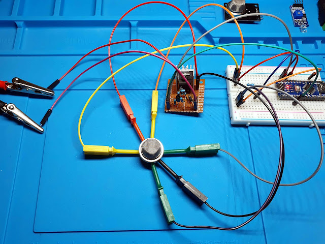
I managed to wire the power supply, the sensor and an Arduino Nano compatible board together. It looks ugly, yet it works.
Test code
I wrote a basic sketch to print voltage readings on serial port so I would later plot them on a graph.
void setup() {
  Serial.begin(115200);
  pinMode(A0, INPUT); // analog input
  pinMode(2, OUTPUT); // voltage switch
}

void loop() {
  float vrl = 0;

  // LPG measurement
  digitalWrite(2, LOW); // 5V
  for (uint8_t i = 0; i < 60; i++) {
    vrl = 5 * analogRead(A0) / 1023.0;
    Serial.print("5 ");
    Serial.println(vrl, 2);
    delay(1000);
  }

  // CO measurement
  digitalWrite(2, HIGH); // 1.4V
  for (uint8_t i = 0; i < 90; i++) {
    vrl = 5 * analogRead(A0) / 1023.0;
    Serial.print("1.4 ");
    Serial.println(vrl, 2);
    delay(1000);
  }
}
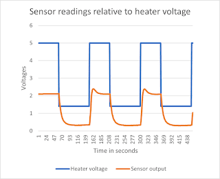
Once every second the analog value is reported over serial port. Heater voltage is set to 5 V for 60 seconds, then switched to 1.4 V for the next 90 seconds and so on.
Results
I can't say the results surprised me. I copied data sent over a few minutes, pasted in spreadsheet software (Excel) and plotted a graph. The sensor output is very similar to the left part of the datasheet graph, when sensor is placed in clean air.
Initially I said LM317 is a bad solution because it dissipates a lot of heat. Well, it is not quite true for this usage scenario. When heater voltage is high (5 V), current is slightly more than 100 mA. When low, my cheap power supply reports 0.00 A (obviously there is a small current flowing, but no more than 42 mA (1.4 V / 33 ohms). The small heatsink you see in the photo above reaches about 30 degrees Celsius.
Conclusion
Electronic module designers should always follow datasheet guidelines and create a module which allows making use of all the features of the device they're integrating. In the situation explained above, the sensor is not very useful in the limited configuration provided by the module PCB.
Note that most sensors from MQ family use heaters powered with constant 5 V. Only the CO sensors require high and low heater voltage. Module PCB was probably designed for the other sensors and later, both MQ-7 and MQ-9 were placed on the common module PCB, without taking into account their different usage.
There will be a follow-up post where I will build something more usable (on a PCB) and try to compute some useful ppm. Here is the datasheet of MQ-7 and MQ-9.


No comments :
Post a Comment
Please read the comments policy before publishing your comment.