How to power MQ gas sensors and measure their resistance using Arduino ADC
MQ-2 is a gas leakage detecting sensor with good sensitivity to a wide range of gases. Since you can get most MQ sensor on ready-made modules, people are interfacing those with development boards. However, the modules are far from perfect. Some of the sensors require variable heater voltages. This is not the case for MQ-2. Since I own a module with this sensor and it can probably be used as is, I decided to make some tests while I'm waiting a PCB for MQ-9 to be manufactured and shipped.
In the previous post I explained why modules with MQ-7 and MQ-9 are no good. Now, I'm about to discover the same for MQ-2. I thought I could use the module as is, since I am more interested in finding a method of computing useful data from the analog output of the sensor. With an Arduino compatible board and an MQ-2 module I will attempt to get ppm values. But not before some parts swapping.
 |
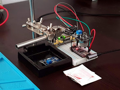
| MQ-2 test fixture, with sensor exposed to alcohol |
Hardware
The module uses a simple circuit. There are variations of parts placement, and some manufacturers added a power indicator LED, but the heater circuit remains the same.
 |
| MQ sensor module PCBs |
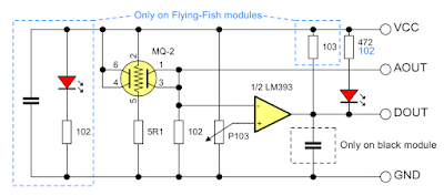
The left module is the one with MQ-2 sensor. Heater is wired in series with a 5.1 ohm resistor. The same is true for the Flying-Fish module on the right (which had an MQ-9 on it). It has an additional power LED and a 10k pull-up resistor on digital output. On both modules, the sensor load resistor (RL) is only 1 kilo-ohm... This is the schematic:
 |
| Gas sensor V1.3 and Flying-Fish module schematic |
I'm not going to use it like this. The resistor placed in series with heater will get shorted. The other resistor, RL, will be removed and replaced with something suitable. But what value should I use? And so, we get to datasheet issue. I was able to find two datasheets from different manufacturers.
Winsen did measurements with RL=4.7k and generated sensitivity curves relative to sensor resistance in clean air. On the other hand, Hanwei used RL=5k to produce sensitivity curves relative to sensor resistance in 1000 ppm Dihydrogen gas. More than this, they recommend using RL=20k. In the end I used RL=4.7k because this was already on module PCB (it was the LED current limiting resistor). All I did was move it with a hot air tool.
 |
| MQ-2 sensor module modified with RL=4.7k |
The LED is no longer working, but I don't care about it. I soldered the 1k resistor which was initially used as RL in series with LED. So, it is working again. It is time to connect this module to a microcontroller. On AOUT pin we measure the voltage across RL. Using this, Rs (sensor resistance) can be computed. Starting from the formula of a resistive voltage divider, we get:
If this looks ugly, I can say it is only the beginning. I wired the sensor to an Arduino Nano compatible board, with its analog pin to A0. As a side effect of reducing the value of the LED series resistor, it lights more brightly. Let's start with the basics and get Rs value. Well, not so fast... The current drawn by heater resistor causes a voltage drop on my USB bus. I measured about 4.5 volts. The development board still works but computed Rs with presumed 5 V is wrong. So is heater voltage. In these conditions I did expose the sensor to isopropyl alcohol and Rs dropped significantly. Anyway, I had to get an external power supply and use it for ADC reference too.
 |
| MQ-2 test fixture schematic |
Source code
Now all I have to do is read ADC value on A0 and use the above equation to get Rs. This is done in 20 lines of code.
const float VCC = 5.0; // supply voltage and ADC reference
const float RL = 4700.0; // load resistor value

int VRLadc = 0; // ADC value (0..1023)
float VRL = 0.0; // computed voltage at ADC input
float Rs = 0.0; // sensor resistance

void setup() {
  analogReference(EXTERNAL);
  pinMode(A0, INPUT);
  Serial.begin(115200);
  delay(5000);
}

void loop() {
  VRLadc = analogRead(A0);
  VRL = VRLadc * VCC / 1024.0;
  Rs = (VCC - VRL) * RL / VRL;
  Serial.print("Rs:");
  Serial.println(Rs, 1);
  delay(1000);
}
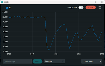
The only thing that is special is the setting of analog reference to external. Other than this, just an endless loop which sends Rs over serial port, ready to be plotted using Arduino IDE Serial Plotter. Here is how it looks when I place the sensor near alcohol vapors.
 |
| Rs variation when exposed to alcohol |
I couldn't get a stable low Rs probably because isopropyl evaporates very fast. As you can see, Rs is nearly 22 kilo ohms in clean air at room temperature. The sensor wasn't powered for at least 48 hors before, so don't take this value into account.
Conclusion
In this post I explored a module with MQ-2 gas sensor and modified it to properly drive the sensor. With simple Arduino code we can compute the sensor resistance. I will try to convert this to ppm values in the next post. I have to extract sensitivity data from datasheet for this purpose.
- MQ-2 datasheet from Hanwei Electronics Co., Ltd.
- MQ-2 datasheet from Zhengzhou Winsen Electronics Technology Co., Ltd.


No comments :
Post a Comment
Please read the comments policy before publishing your comment.