Send temperature and humidity data to a weather station over 433.92 MHz, OOK modulated with FS1000A module
In a previous post I used a software defined radio (SDR) to analyze and decode data transmission over 433.92 MHz of a simple weather station. As I mentioned then, the indoor unit can receive data from up to three outdoor units. I found that outdoor units use basic OOK modulation to send data to indoor unit. Knowing this I can make my own outdoor unit using a 433 MHz transmitter module controlled by an Arduino.
Obviously, I had to use a temperature and humidity sensor such as DHT11, DHT22, AM2302 to get environment parameters. I emulated full original outdoor unit functionality by adding a display and a push button to trigger immediate transmission of data to indoor unit.
 |
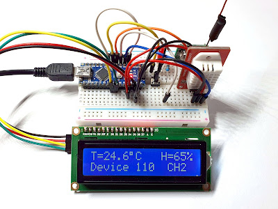
| Arduino based data transmission device |
Electronics
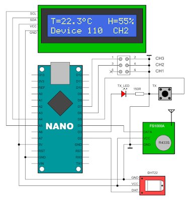
The device is controlled by an Arduino Nano compatible board. For the simplicity of the schematic, I used an alphanumeric LCD fitted with I2C adapter. I also added the red LED to signal RF transmission, as it is on original unit.
 |
| Schematic of prototype |
The outdoor units can be configured to transmit data on three channels. The “channel” is a bit in the data stream. I included a jumper to set channel. The RF module is part of a RX-TX kit. I got acceptable results with this TX module (FS1000A), yet I would recommend you use other type. There are some problems with it.
Output power is way lower than the original unit of the weather station. Note that I powered FS1000A from 5 V, yet it accepts up to 12 V. Maybe, at 12 V it would provide more output power. I built a simple antenna using some copper wire, after instructions of Ben Schueler.
Another thing to mention is that frequency drifts mostly because of no shielding. It should be quite stable, since it uses a SAW resonator, R433S type.
 |
| Schematic of FS1000A module |
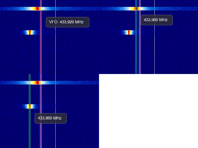
Speaking of SAW resonator, according to datasheet, it has a frequency of 433.92 MHz. More or less (75 kHz more or less). I found mine to oscillate on 433.86 MHz (which is within the specifications). The RF signal can still be received by main unit. But, given the lower output power and this frequency shift, TX range is severely reduced.
 |
| Frequency of original outdoor unit vs. FS1000A module |
While making some signal recordings using the SDR of original outdoor unit and my device, I also found this FS1000A has (probably unintended) slow start and stop. When switching data pin to HIGH, it gradually increases the output power until it reaches maximum. Gradual decrease is also noted when switching back to LOW. The oscillator is off when data input is LOW.
To overcome this effect, I had to alter bit times to make my signal understandable for the weather station.
Code
Controlling this with Arduino is pretty easy. RF transmission of FS1000A module can only be turned on and off using DATA pin. This makes it suitable for OOK modulation only (on-off keying). As I shown in the previous post, the original device encodes data using pulse distance modulation as follows: a 500 µs carrier burst followed by 1000 µs pause represents bit 0, while a 500 µs carrier burst followed by 2000 µs pause represents bit 1. There is also a space (or a sync bit) represented by 500 µs carrier burst followed by 4000 µs pause. This is used between data packets. Starting with the basics, this is the function which generates the signal for bit 0 or 1:
// ***** Generate the pulse for a single bit *****
void tx_bit(byte onPin, bool b)
{
  digitalWrite(onPin, HIGH);
  delayMicroseconds(PULSE_HIGH);
  digitalWrite(onPin, LOW);
  if (b == true)
    delayMicroseconds(PULSE_ONE);
  else
    delayMicroseconds(PULSE_ZERO);
}
Next we need to generate the 36-bit packet containing 8-bit device ID (house code), battery status bit, channel bits, 12-bit signed temperature multiplied by 10, 4-bit always 1111 and 8-bit humidity.
 |
| Data bits |
While analyzing the signal of the original unit, I discovered it skips first 4 bits of device ID on every first packet transmission. This is why the next function takes an argument which is set to true only on first packet transmission to skip ID bits.
// ***** Generate bitstream (36 bits) *****
void tx_data(byte onPin, bool first = false)
{
  int idx;

  // send ID
  for (first ? idx = 3 : idx = 7; idx >= 0; idx--)
  {
    tx_bit(onPin, dev_id & (0x1 << idx));
  }

  // send battery state
  tx_bit(onPin, dev_batt);

  // send zero
  tx_bit(onPin, LOW);

  // send channel
  tx_bit(onPin, dev_ch & 0x2);
  tx_bit(onPin, dev_ch & 0x1);

  // send temperature (12 bits)
  int16_t t12 = t * 10.0f;
  for (idx = 11; idx >= 0; idx--)
  {
    tx_bit(onPin, t12 & (0x1 << idx));
  }

  // send 1111
  tx_bit(onPin, HIGH);
  tx_bit(onPin, HIGH);
  tx_bit(onPin, HIGH);
  tx_bit(onPin, HIGH);

  // send humidity
  uint8_t h8 = (uint8_t)h;
  for (idx = 7; idx >= 0; idx--)
  {
    tx_bit(onPin, h8 & (0x1 << idx));
  }
}
The above generates a single data packet. In needs to be repeated 10 times, including sync bit between each packet. Note the first packet should skip ID bits. This is what the next function does.
// ***** Generate full signal (36 bits repeated 10 times) *****
void full_broadcast(byte onPin, byte repeat)
{
#ifdef COMPLETE_TX
  tx_data(onPin, false);
#else
  tx_data(onPin, true);
#endif

  // sync bit
  digitalWrite(onPin, HIGH);
  delayMicroseconds(PULSE_HIGH);
  digitalWrite(onPin, LOW);
  delayMicroseconds(PULSE_SYNC);

  for (int i = 1; i < repeat; i++)
  {
    tx_data(onPin);

#ifndef COMPLETE_TX
    if (i + 1 == repeat)
      break; // do not send sync after last TX
#endif

    // sync bit
    digitalWrite(onPin, HIGH);
    delayMicroseconds(PULSE_HIGH);
    digitalWrite(onPin, LOW);
    delayMicroseconds(PULSE_SYNC);
  }
}
Also, after last packet there is no sync bit. I included a preprocessor directive in the code which allows sending complete data packets (COMPLETE_TX). For this device, this should not be defined. The 10 packets are sent every 56.75 seconds. This is a strange time interval, but this is what I measured on recorded signals from original unit.
According to rtl_433 signals database, the device ID (house code) is randomly changed every time batteries are changed in the unit. I did set it using random() but it seems to always default to 110.
Note that at the beginning of the code there are the slightly modified pulse times. I had to increase carrier burst to 550 µs then decrease space times a bit to get a proper output signal.
Overview
It is not hard to transmit OOK data using Arduino, however the choice of FS1000A as the radio module is not the best. Frequency tends to drift, transmission range is rather low and because of its simplicity, the 433.92 MHz carrier is switched on and off with a delay.
Full source code for Arduino framework over PlatformIO can be downloaded here. Using Arduino or ESP8266 you can also build a receiver.


Awesome article, works perfectly as described, thanks ! (Tested with a Fetanten weather station)
ReplyDeleteGreat! Thank you for feedback!
DeleteHow to receive data from Weather Station's TX ?
ReplyDeleteI plan to do that too, but I haven't got the time.
DeleteOne of the reasons you are seeing that turn-on delay in the output of the FS1000A may be that you have it connected wrong (and it's not your fault!). The pins on those modules are often mislabeled. They are labeled (looking from the edge of the board inward toward the resonator), Vss Data GND. But that is wrong. It should be Data Vcc Gnd. So when you connect it up according to how it is labeled, it does work, but you are essentially turning the whole circuit on and off every time. If you swap the Data and Vcc connections, you are only switching that lower NPN transistor on and off, as intended. I got much better range and more reliable transmission when I swapped those connections.
ReplyDeleteThank you for this article. It is by far the clearest and most informative I have found. I re-implemented this in Python, but unfortunately it is not working for me. The signal seems to be frequency shifted, or at least I hope that this is the problem. I have no idea how to compensate that with the FS1000A. While I am happy to share, I thought that you probably don't want me to post the code here. Any ideas how to tackle this???
ReplyDeleteFS1000A is the worst possible transmitter and its frequency tends to drift. I think H34A could be a better alternative.
Delete