Some minor tweaks to improve movement range of CNC 3018 Pro Z axis and make the machine more reliable with thread lock adhesive
The first thing people tell you when you start doing CNC is that you will break some bits. It happened to me too. I checked the gcode before sending it to CNC so I wouldn't ram the bit into the work piece or the base plate. But, with my CNC 3018 Pro another thing happened. The spindle could no longer be lifted (Z axis movement failed).
CNC 3018 comes as a kit. With the exception that in the newer batches of this product, they decided to ship it with preassembled Z axis assembly. Obviously, I assembled the machine and didn't pay any attention to the Z-axis. Until I had to. The lead screw slipped from the shaft coupler during a job and the bit nearly got to the base plate before breaking. Then I realized there were some problems with the Z axis assembly.

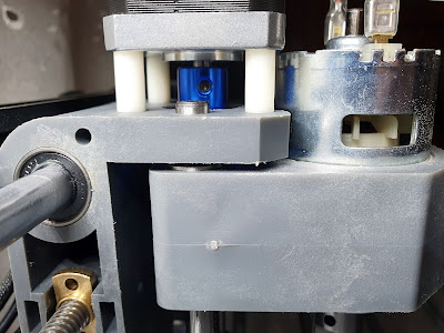
Spindle at its maximum Z height with short shaft stepper
One of the screws locking the shaft coupler to T8 lead screw completely fell. I did find it on the spindle motor held there by its permanent magnets. Strange things happened when I tried to put it back. I was able to screw it way too much. Because the lead screw was not inserted enough in the coupler. Take a look at the schematic representation of initial setup.

Shaft coupling in the Z axis of CNC 3018
In the initial setup, the coupler was over-inserted on motor shaft, leaving too less space for the T8 lead screw. They had two reasons to do this: in this way anyone has access to coupler screws and the higher the coupler is, the less is Z axis movement limited. Z axis movement was limited to about 38 mm because T8 nut hits shaft coupler before spindle holder can reach Z gantry.
The first idea that came to my mind was to make a proper coupling of the lead screw to motor shaft. I had to take off the stepper motor for this, which is by far the hardest part. It is fixed with Philips PH2 screws inserted from below in a limited space where you can hardly reach with any kind of screwdriver. With a smaller screwdriver (either PH1 or flat head) I was able to drive the screws in an oblique direction. Putting it all back is even harder.
So I did the coupling fix represented in the schematic drawing above (middle). Then I had realized the nut in spindle holder would ram into the coupler at a lower position. I limited Z movement to 35 mm. At its highest position, the spindle chuck was slightly lower than the lower edge of Z gantry. And this was not what I want, since the Z axis movement is low enough.
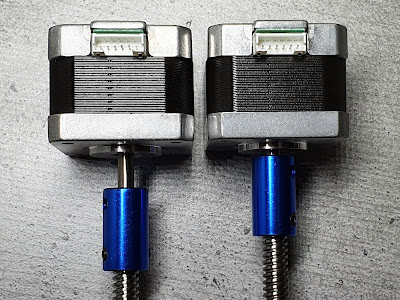
Then I had one idea to shorten motor shaft (24 mm initial length). But I looked at the X and Y axes stepper motors. Those had shorter shafts by default (15 mm). And, good enough, all motors are same model, with same features, except shaft length. So I decided the best thing to do was to replace Z axis motor with Y axis one. And if I push the T8 nut as low as possible, I can obtain the advertised 40 mm movement on Z axis. Then a 9 mm longer shaft would cause no issues on Y axis.
Because lead screw is now slightly upper than before, its lower end no longer reaches the slot in the Z gantry. This causes no issues.

The difference between original Z axis stepper with 24 mm shaft (left)
and X/Y axis stepper with 15 mm shaft (right)
Since I had to unscrew shaft couplers I decided to make some other modifications to prevent any future slip of coupler from shaft or of the lead screw from coupler.
I made some notches on the shafts and on the lead screws for the coupler locking screws. I did this for one of the locking screws, on each side (there are two locking screws for shaft and another two for lead screw). I used a rotary tool with a cutting disc for this purpose. Another good thing to make CNC 3018 more reliable is to add thread locking adhesive on the coupler screws. There are methacrylate based adhesives for this purpose which allow unscrewing if needed (Loctite® 243, Bison Lock Bond). Do not use common "SuperGlue" which is cyanoacrylate.

Shaft couplers are fixed with thread lock adhesive after a notch is made on shafts and lead screws
I don't think this is needed for frame screws. But you should apply glue on all of the rotating parts which have screws (ER11 chuck and shaft couplers). This is the best method to prevent unscrewing issues. I did so. And I previously made notches for the coupler locking screws on all three axes. I skipped the spindle motor since I couldn't pull the chuck from its axis. But I unscrewed the locking screws of the chuck and added Loctite 243 before screwing them back.
Some people make significant modifications to Z axis. They replace spindle motor with a bigger one or they completely replace Z gantry with a metallic assembly. Unfortunately none of these methods improve Z axis movement distance or allow more than 40 mm height. I don't take into consideration doing such modifications, yet I want to make the most out of my CNC 3018, with its known features.
If you want to spend some money, there is even a better upgrade. All stepper-coupler-screw assemblies can be replaced with lead-screw steppers (although T8x4 mm lead screws on steppers are not as common; the linked ones are T8x8 mm lead). Did you have any issues with the shaft couplers on CNC 3018?


Having a similar issue with mine, its all decent parts but stil doesnt lock in nicely for larger work. fine for smaller things, just comes loose with larger work
ReplyDelete