How to add diodes or inductors for RF input protection and the possibility to power SPF5189Z LNA boards over coaxial cable
The SPF5189Z is a high-performance pseudomorphic high-electron-mobility transistor (pHEMT) monolithic microwave integrated circuit (MMIC) low noise amplifier (LNA) designed for operation from 50MHz to 4000MHz. Since the chip has a small SMD capsule and to avoid damage from improper soldering tools I bought a couple of boards based on SPF5189Z. With its large bandwidth, this LNA can be used to improve the reception of my RTL-SDR. Usage is not limited to SDR, this amplifier can boost FM radio or TV signals. TO get the best results, I had to mount it as close as possible to the antenna. By studying the datasheet and looking at the boards I have bought, I realized that design wasn't quite made for what I wanted to achieve.
First of all, power is supplied separately, not over coaxial cable. To fix this, I would have to build a bias tee circuit. But, before doing this, I took off the metal cover off only to find that to power SPF5189Z, they used a bias tee circuit. So, I would have to add another one just to redirect DC back to the RF line. Secondly, the RF input is capacitor coupled. Just that. No ESD protection. I'll have to do something with this too.

The SPF5189Z LNA board
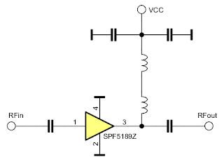
The PCB in the above photo follows a simple schematic. It's enough to take off the metal cover to see the four capacitors and two inductors beside SPF5189Z.

Schematic of the green LNA board based on SPF5189Z
I want to install this outdoors as close as possible to the antenna. Therefore I will disable the included bias tee circuit. In this way, I can easily power the LNA through the coaxial cable, with an indoors bias tee circuit. When it comes to input protection, there are multiple solutions. I could use a low pass filter which, in its simplest form, is an inductor connected to ground. For frequencies higher than 50 MHz, a 680 nH inductor is suitable.
There is also the possibility to use special transient voltage suppression (TVS) diodes. To have a minimum impact on the performance of the LNA, such diodes should have low capacitance. To ensure protection, fast response time is required. This application note from Infineon is about antenna input ESD protection with diodes.

SPF5189Z LNA with ESD input protection (left - TVS diodes; right - low pass filter)
Another usage scenario could be for TV reception, with a 300 ohms balanced antenna. You can replace the input diodes with the matching transformer (balun). I've written about the construction of such a balun here. Both antenna connections are wired to ground via RF transformer.

SPF5189Z LNA with 300 ohms balanced input
Disabling the included bias tee circuit requires removing the coil which supplies DC to LNA and also to remove the output capacitor. On the pads of this capacitor add a solder bridge. You may remove all the remaining parts of the bias tee, leaving on the board only SPF5189Z and the RF input capacitor. Protection diodes or filter inductor is connected from RFin to GND, anywhere before the capacitor. Use whatever parts you want, but keep in mind their high-frequency response. SMD diodes are recommended and should be soldered directly to the SMA connector's pins.
These solutions will somewhat lower the performance of the LNA (depending on what parts you use, only parts of the RF spectrum will be affected), but they will improve the overall LNA reliability in an outdoors setting.


Hi,
ReplyDeletedid you do some comparissons beteeen SPF5189Z boards and other lna (nooelect for example) regarding noise, gain and linearity?
Nooelec says that their lna 100812 is way better then the SPF5189z but according to the datasheets it's not.
Is a case needed to use this board in a waterprotected tube outdoor? I have a bias t SDR but between lna and SDR I use a saw filter, so don't know if power over coax is possible and how.
Greetings
Peter
Hello Peter. I didn't do any comparisons. Unfortunately my SPF5189z LNA is no longer working. I had it mounted outdoors, very close to the antenna, water protected, but not in a metal case. These devices seem to be very sensitive to electrostatic discharges (lightning) if the input is not properly protected and the ground is not earthed.
DeleteIf you feed power through the coax I recommend leaving the original bias circuit there, unless it has a resonance or something on the frequency of interest. It will still provide relatively low impedance decoupling for the MMIC, even if the power is not supplied through it.
ReplyDeleteHello everybody,
ReplyDeletefor statics input protection without signal loss at high frequencies,
you can add a BAV99 smd low capacitance double-diode at the antenna input, just before input capacitor, as done with SDR-TNT USB-keys.
For current limitation (I<100mA) which fries the LNA, it's STRICTLY NECESSARY to power the device under 5v across a 33ohms 2w resistor as current limitation is the first purpose of a bias T.
You can power the lna from home-end of coax, feed the LNA via the coax cable line and then, power the LNA located near the roof antenna, across the 33 ohms resistor, with voltage picked-up just after the lna-output capacitor.
F5OPV
Thank you for this valuable information.
DeleteJust copy this one - https://www.rtl-sdr.com/wp-content/uploads/2018/08/WidebandLNA_PCB_Store.jpg
ReplyDeleteHi there, I'm glad I found this since I am interesting in LNA board. But before purchasing components, I'd like to run a simulation first. Can you give me the info of values of capacitor and inductor? Thanks a bunch !!!
ReplyDeleteI don't know those values.
Delete