How to build a tachometer with a slotted optical switch and an Arduino board. Simple sketch based on interrupts.
The piece that will block IR light will be a flange with a slot (a cutout area from the disc). When this passes through the switch's slot, the light reaches the receiver diode. Therefore, rotations are translated into a digital signal with a constant duty factor, dependant on flange configuration. The frequency of this signal needs to be measured and converted into RPM.
 |
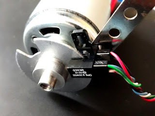
| 775 motor fitted with optical switch |
I used for this project an OPB930 optical switch which I found in my parts bin. You won't find this exact part number, but optical endstop switches designed for use at 3D printers are widely available for less than 1USD/piece. If you want, you can even build this yourself with an IR LED and IR photodiode.
 |
| Slotted wheel and optical switch mounted on motor |
 |
| Flange coupler and types of discs you can use for RPM counting |
 |
| Connect the optical switch to Arduino pin 2 |
 |
| Measured RPM of 775 motor |
  noInterrupts();
  uint32_t rpm = rot * 60000 / (millis() - measureTime);
  rot = 0;
  measureTime = millis();
  interrupts();
Interrupts are disabled during RPM computation. 60000 is divided by time in milliseconds passed since previous computation [millis() - measureTime]. This converts ms to minutes. The value is then multiplied by count of rotations (rot). This counter is cleared and measureTime is updated.
The software is incredibly simple.
#include <LiquidCrystal.h>

LiquidCrystal lcd(8, 9, 4, 5, 6, 7);

volatile uint32_t rot; // rotation count
unsigned long measureTime = 0;

void setup() {
  pinMode(10, INPUT); // for LCD shield
  pinMode(2, INPUT);

  lcd.begin(16, 2);
  lcd.print("   Tachometer   ");
  delay(500);

  attachInterrupt(0, addRotation, RISING);
}

void addRotation() {
  rot++;
}

void loop() {
  delay(1000);

  noInterrupts();
  uint32_t rpm = rot * 60000 / (millis() - measureTime);
  rot = 0;
  measureTime = millis();
  interrupts();

  lcd.setCursor(0, 1);
  lcd.print(rpm);
  lcd.print(" RPM        ");
}
LCD pins are configured for the LCD-keypad shield.
This mode of measurement can be used as long as RPM is greater than 60. Each second, at least one rotation must happen for accurate readings. I prefer to use this method of counting rotations over a larger period of time (about 1 second), instead of measuring the duration of a single rotation.


No comments :
Post a Comment
Please read the comments policy before publishing your comment.