How to configure STM32 "blue pill" development boards for programming with Arduino IDE. Instructions for Windows and Linux
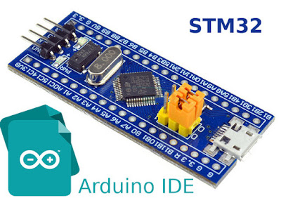
The "blue pill" is a STM32F103 based development board. Although it is less popular, the board is cheaper than the Arduino Nano. More than that, STM32F103 is a device with Cortex-M3 ARM CPU that runs at 72 MHz, 20 kB of RAM and 64 or 128 kB of flash memory. The microcontroller (MCU) has USB port, two serial ports, 16 bit PWM pins and 12 bit ADC pins. It runs at 3.3V, but some of its pins are 5V tolerant.
Programming the board can be simplified using the popular Arduino IDE. But before this, an Arduino-like bootloader must be flashed to the board. This can be done via serial port or using the debug interface of the MCU with ST-Link tool. There are also some small hardware issues with Chinese boards that need to be fixed. This post will show a straightforward guide for setting up this board to work with Arduino IDE on Linux and Windows. The instructions below are based on STM32duino wiki [down?] documentation.
If you decide to use ST-Link programmer, there is no need for a bootloader. If you prefer a different IDE, see here how to develop for STM32 in PlatformIO. You have access to multiple frameworks if you go for PlatformIO.
Hardware issues
STM32duino wiki contributors have reported that some of the boards came with poor soldering of the micro-USB connector. Also some of them have USB D+ pulled up with 4.7 k or 10 k resistors which may cause the USB port not to work on some computers. My board had both these issues. I soldered the USB connector. Even though my computer recognized the USB device and so may yours, I highly recommend pulling up D+ with 1.5 k if you use USB port.
Look on the back of the board and locate R10. If it's 10 k (marked 103) you can add 1.8 k parallel resistor to obtain 1.5 k equivalent resistance. If it's 4.7 k (marked 472), a 2.2 k resistor is suitable for parallel connection. Don't worry, you don't have to do SMD soldering as D+ is connected to PA12. Just solder the resistor between PA12 and 3.3V pinheader pads.
Another thing that is good to know, is what pin the LED connects to. Depending on this you will choose the correct bootloader.

Blue pill hardware check
Go to STM32duino GitHub repo and look for the bootloader. Roger Clark offers many bootloaders for different boards. If your board has the green LED connected at PC13, you need the bootloader built for this configuration: generic_boot20_pc13.bin. Download the bootloader for your board and keep reading.
Arduino IDE
The IDE doesn't come with default support for STM32 boards. This step is common to all operating systems, so let's do it now. Launch Arduino IDE, go to File - Preferences, and add the following Boards Manager URL:
http://dan.drown.org/stm32duino/package_STM32duino_index.json
Click OK to close the dialog.
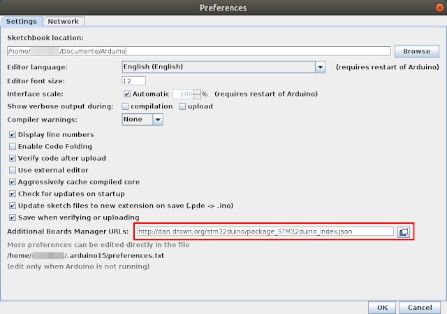
Arduino IDE - add Boards Manager URLs
Next, go to Tools - Boards - Boards Manager. In the dialog that appears, search for STM32 and choose STM32F1xx for "blue pill". If your board uses a different chipset (i.e. STM32F3) select that one. Install it.
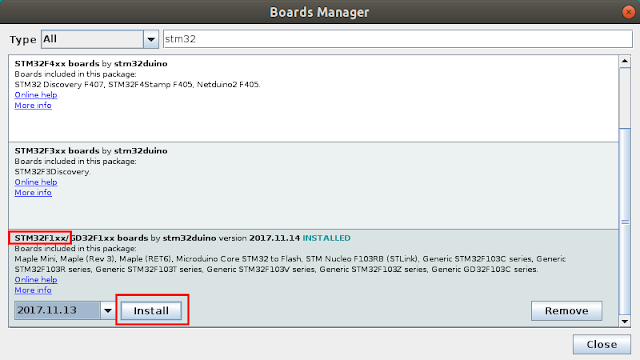
Arduino IDE, Boards Manager - install new board
Before actually uploading sketches to the board via USB port, it needs the STM32duino bootloader. I will be using a ST-Link v2 clone to burn the bootloader. The connection to the development board is straightforward, using SWCLK, SWDIO, GND and 3.3V pins. Connect them using the included jumper cables that came with the ST-Link. Do not power the development board from other source or USB port! It will get its power from the programmer. Right now, you can plug the programmer into an USB port and program the board straight from Arduino IDE using STlink upload method.
If you don't want to use the programmer all the time and prefer to use the micro USB port to upload software to board, install the bootloader. I found this method not quite reliable, so I'm uploading sketches directly to flash with ST-Link programmer. At the end of the post I share some information about it. Anyway, you may give it a try. Move the jumper to set BOOT0 to 1. Plug the ST-Link into an USB port. From now on, configuration process is different depending on operating system.
Windows
Needed tools can be found at ST. You need STSW-LINK009 (this is the Windows driver) and STSW-LINK004 (the programming utility). You need to make an account to download them. Use the included dpinst tools or the bat script to install the driver. After the driver is installed and the ST-Link adapter is recognized by the computer, install and launch STM32 ST-LINK Utility.
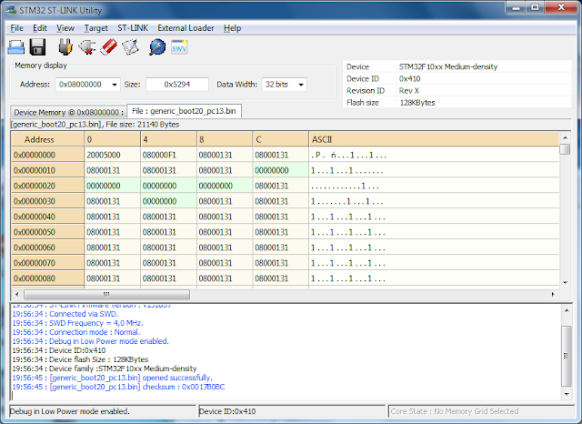
ST-Link Utility
Use the File menu to open the bootloader bin file you downloaded earlier. Next, connect to programmer (use the plug icon on the main toolbar, or Target - Connect) then choose Erase and Program option from the same menu. The bootloader will be burned to MCU Flash memory.
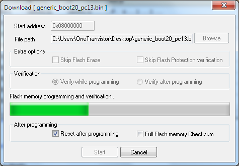
Downloading bootloader
While the bootloader is downloading to MCU, you will see the programmer LED flashing. When it is done, you can disconnect the board from programmer, change back BOOT0 to 0 and connect it using board's USB. Of course, it needs Windows drivers which can be found in the Arduino_STM32 package prepared by Roger Clark. You don't need to download the entire repository just for the drivers. Most of the files contained in this repository were automatically downloaded by Arduino IDE when you added the board support (but not the driver). Here is a driver only archive. Extract it and run install_drivers script. When you reset the board, for a short moment of time while bootloader is running, it appears as DFU device, then switches to serial port.
Linux
ST offers no GUI tools to program the board from Linux. But, when you downloaded the board with Arduino IDE, you also downloaded the tools to program the board using ST-Link adapter. In your home folder, open hidden .arduino15 folder (nautilus ~/.arduino15). Browse to packages/stm32duino/tools/stm32tools. Here you will find a folder named like the STM32 package version (i.e. 2017.11.14). Open it, then linux subfolder. There should be an install.sh script here. Run it from terminal with root permissions (sudo ./install.sh). You just installed udev rules for ST-Link and board. It is now recommended to log off then back in or restart computer.
Open again ~/.arduino15/packages/stm32duino/tools/stm32tools/2017.11.14/linux, go to stlink folder. Make sure BOOT0 is set to 1 and run ./st-info --probe. You should see something like this:
Found 1 stlink programmers
 serial: 573f...
openocd: "\x57\x3f\x..."
  flash: 131072 (pagesize: 1024)
   sram: 20480
 chipid: 0x0410
  descr: F1 Medium-density device
This is an indication that everything is OK and you can proceed burning the bootloader with the following command:
./st-flash --reset write ~/Desktop/generic_boot20_pc13.bin 0x8000000
Adjust the command with the correct path to bootloader file. Here is the output of this command:
2017-11-19T12:32:28 INFO src/common.c: Loading device parameters....
2017-11-19T12:32:28 INFO src/common.c: Device connected is: F1 Medium-density device, id 0x20036410
2017-11-19T12:32:28 INFO src/common.c: SRAM size: 0x5000 bytes (20 KiB), Flash: 0x20000 bytes (128 KiB) in pages of 1024 bytes
2017-11-19T12:32:28 INFO src/common.c: Attempting to write 21140 (0x5294) bytes to stm32 address: 134217728 (0x8000000)
Flash page at addr: 0x08005000 erased
2017-11-19T12:32:29 INFO src/common.c: Finished erasing 21 pages of 1024 (0x400) bytes
2017-11-19T12:32:29 INFO src/common.c: Starting Flash write for VL/F0/F3 core id
2017-11-19T12:32:29 INFO src/common.c: Successfully loaded flash loader in sram
 20/20 pages written
2017-11-19T12:32:31 INFO src/common.c: Starting verification of write complete
2017-11-19T12:32:31 INFO src/common.c: Flash written and verified! jolly good!
That's it. Disconnect the programmer, move BOOT0 back to 0 and connect the board using its USB port.
Here is what happens when you reset (plug in) the board. First the DFU device appears then the USB serial port (/dev/ttyACM0).
[ 1146.407442] usb 7-1: USB disconnect, device number 2
[ 1172.671329] usb 7-1: new full-speed USB device number 3 using uhci_hcd
[ 1173.058344] usb 7-1: New USB device found, idVendor=1eaf, idProduct=0003
[ 1173.058347] usb 7-1: New USB device strings: Mfr=1, Product=2, SerialNumber=3
[ 1173.058349] usb 7-1: Product: Maple 003
[ 1173.058351] usb 7-1: Manufacturer: LeafLabs
[ 1173.058352] usb 7-1: SerialNumber: LLM 003
[ 1173.687380] usb 7-1: USB disconnect, device number 3
[ 1174.407316] usb 7-1: new full-speed USB device number 4 using uhci_hcd
[ 1174.587353] usb 7-1: New USB device found, idVendor=1eaf, idProduct=0004
[ 1174.587357] usb 7-1: New USB device strings: Mfr=1, Product=2, SerialNumber=0
[ 1174.587359] usb 7-1: Product: Maple
[ 1174.587361] usb 7-1: Manufacturer: LeafLabs
[ 1174.628070] cdc_acm 7-1:1.0: ttyACM0: USB ACM device
[ 1174.629510] usbcore: registered new interface driver cdc_acm
[ 1174.629513] cdc_acm: USB Abstract Control Model driver for USB modems and ISDN adapters
Sketches are uploaded while in DFU mode (device 1eaf:0003).
Uploading a sketch
Launch the IDE and choose the board. For a generic "blue pill", here is the default configuration:
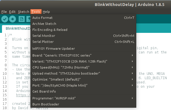
STM32 Generic board in Arduino IDE
On Windows, only the port is different (COMx). Open a sample sketch and compile it. From my experience, on Windows you can just press Upload button to reset the board and burn the sketch binary. But, on Linux I had no luck with automatic reset. I make sure the sketch is compiled then I reset the board by pushing the button and I click quickly on Upload button in Arduino IDE. Otherwise, uploading fails.
This is the output in Arduino IDE:
Sketch uses 13028 bytes (9%) of program storage space. Maximum is 131072 bytes.
Global variables use 2824 bytes (13%) of dynamic memory, leaving 17656 bytes for local variables. Maximum is 20480 bytes.
No valid DFU suffix signature
Warning: File has no DFU suffix
dfu-util 0.7

Copyright 2005-2008 Weston Schmidt, Harald Welte and OpenMoko Inc.
Copyright 2010-2012 Tormod Volden and Stefan Schmidt
This program is Free Software and has ABSOLUTELY NO WARRANTY
Please report bugs to dfu-util@lists.gnumonks.org

Filter on vendor = 0x1eaf product = 0x0003
Opening DFU capable USB device... ID 1eaf:0003
Run-time device DFU version 0110
Found DFU: [1eaf:0003] devnum=0, cfg=1, intf=0, alt=2, name="STM32duino bootloader v1.0  Upload to Flash 0x8002000"
Claiming USB DFU Interface...
Setting Alternate Setting #2 ...
Determining device status: state = dfuIDLE, status = 0
dfuIDLE, continuing
DFU mode device DFU version 0110
Device returned transfer size 1024
bytes_per_hash=260
Copying data from PC to DFU device
Starting download: [##################################################] finished!
state(8) = dfuMANIFEST-WAIT-RESET, status(0) = No error condition is present
Done!
Resetting USB to switch back to runtime mode
Waiting for /dev/ttyACM0 serial...Done
If dfu-util reports no DFU devices, you didn't reset the board at the right time. This means sketch was not uploaded to board. The Linux issues seems to be related to driver implementation because shortly after a failed upload (without reset), dmesg reports a failure to set dtr/rts on ttyACM0.
Without bootloader
If this method of uploading a sketch (using the bootloader) is a pain, there are alternatives. I regularly use the ST-Link programmer to upload Arduino sketches to blue pill. No need to manually reset the board, no need to move jumpers. Uploading is faster on Linux than on Windows (I don't know why).
On very rare occasions uploading fails. In this situation I have to move BOOT0 jumper to 1 and upload the sketch. Binaries do not run when BOOT0 is set to 1 therefore I move it back. There are also very rare occasions when blue pill does not reset after upload. I have to push the reset button.
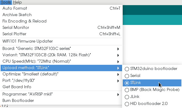
Configure blue pill in Arduino IDE for ST-Link
Programming port of the blue pill has only 3.3V supply. This can be regarded as a good thing, because 5V won't be available on 5V pin so you can be sure you won't supply 5V to a non tolerant pin. But, if you fit the blue pill on the breadboard it's easy to get a 5V supply line from ST-Link using a jumper wire (if you really need it).
Using Arduino IDE with STM32duino bootloader to program the "blue pill" development board isn't the most effective way to develop STM32 based systems, but it's easier than with other development kits. It's recommended to read the API differences and have a look at examples if you will use this method.


Great post, it's the most accurate I found around.
ReplyDeleteI'm on Arch Linux, USB upload using STMduino always fails (45-maple.rules are active). I had success only using STLink (clone).
Similar issues on VSCode+PlatformIO: it doesn't work using DFU but it works with upload_protocol = stlink
I tryed dfu-util --list (v0.7 up to v0.9) and it doesn't show any adapter. dmesg is the same as yours (1eaf:0003 and then 1eaf:0004).
I solved "st-flash: error while loading shared libraries: libusb-1.0.so.0: cannot open shared object file" installing 32bit libusb: pacman -S lib32-libusb
Thanks for sharing your post.
Piero
how i can know the digital and analog pins ?
ReplyDeleteSee this: http://wiki.stm32duino.com/index.php?title=File:Bluepillpinout.gif
DeleteHello,I have flashed the duino bootloader into the blue pill(F103C8T6)however whenever I try to upload code using the USB cable the IDE says the board does not identify as (maple mini)and refuses to upload to the board...I will have a FTDI loader on Fri and will try using it..maybe it will work ..if not to MXCUBE and KILE here I come
ReplyDeleteThanks my friend. The best ever tutorial i have ever found on web. It worked for me. Thanks a lot.
ReplyDeleteHello, I got an error whenever I try to upload program on board. The program I used is the BlinkWithoutDelay program. The error I get is specified below :
ReplyDeleteSketch uses 13140 bytes (20%) of program storage space. Maximum is 65536 bytes.
Global variables use 2832 bytes (13%) of dynamic memory, leaving 17648 bytes for local variables. Maximum is 20480 bytes.
maple_loader v0.1
Resetting to bootloader via DTR pulse
Searching for DFU device [1EAF:0003]...
Found it!
Opening USB Device 0x1eaf:0x0003...
Found Runtime: [0x1eaf:0x0003] devnum=1, cfg=0, intf=0, alt=2, name="STM32duino bootloader v1.0 Upload to Flash 0x8002000"
Setting Configuration 1...
Claiming USB DFU Interface...
Setting Alternate Setting ...
Determining device status: state = dfuIDLE, status = 0
dfuIDLE, continuing
Transfer Size = 0x0400
bytes_per_hash=262
Starting download: [##################################################] finished!
state(8) = dfuMANIFEST-WAIT-RESET, status(0) = No error condition is present
error resetting after download: usb_reset: could not reset device, win error: The system cannot find the file specified.
Done!
How to solve that error?
I need help, please. Thanks in advance.
I solved the problem myself lol
DeleteTurns out I have to move the other BOOT0 to BOOT1 (the right BOOT from the Micro USB perspective).
The error persist but the program ran well.
Thanks! Great tutorial!
You can also flash a bootloader with USB support using a USB-serial dongle:
ReplyDeletehttp://www.zoobab.com/bluepill-arduinoide
no fix for the Linux and need to press reset manually ?
ReplyDeleteUnfortunately, I don't know any fix for that. There is however a modified bootloader which stays in DFU mode for about 10 seconds after reset, so you have enough time to hit the upload button in Arduino IDE. See http://www.zoobab.com/bluepill-arduinoide#toc2
DeleteHi Cornelius,
ReplyDeleteI have the Arduino IDE 1.8.9 on Kubuntu 18.04 and on my laptop with kubuntu 14.04
I have installed STM32 Cores by STMicroelectronics version 1.6.1 on both computers.
I have run ~/.arduino15/packages/STM32/tools/STM32Tools/1.3.0/tools/linux/install.sh in order to install the 45-maple.rules.
After starting the Arduino IDE the upload method doesn't show the STLink option. There isn't a stlink folder under ~/.arduino15 folder either (searched all the tree).
Could you please tell me what steps I did miss?
Thanks.
Pedro.
I can't find the step to install
This tutorial applies to STM32F1xx/GD32F1xx boards by stm32duino. It appears to me that you have installed a different "board" package.
DeleteThanks, Cornelius. And sorry for my late feedback, I was out last week. I will try another package, though the package I installed included the stm32F103 of my bluepill.
Delete$ ./st-flash --reset write ~/Desktop/generic_boot20_pc13.bin 0x8000000
ReplyDelete2021-07-27T07:36:22 INFO src/common.c: Loading device parameters....
2021-07-27T07:36:22 INFO src/common.c: Device connected is: F1 Medium-density device, id 0x20036410
2021-07-27T07:36:22 INFO src/common.c: SRAM size: 0x5000 bytes (20 KiB), Flash: 0x20000 bytes (128 KiB) in pages of 1024 bytes
2021-07-27T07:36:22 INFO src/common.c: Attempting to write 22268 (0x56fc) bytes to stm32 address: 134217728 (0x8000000)
Flash page at addr: 0x08005400 erased
2021-07-27T07:36:22 INFO src/common.c: Finished erasing 22 pages of 1024 (0x400) bytes
2021-07-27T07:36:22 INFO src/common.c: Starting Flash write for VL/F0/F3 core id
2021-07-27T07:36:22 ERROR src/common.c: unknown coreid, not sure what flash loader to use, aborting!: 2ba01477
2021-07-27T07:36:22 WARN src/common.c: Failed to write flash loader to sram!
2021-07-27T07:36:22 ERROR src/common.c: init_flash_loader() == -1
stlink_fwrite_flash() == -1
I am getting unknown coreID error can you help me out solve this?
Are you using the STM32F103C blue pill board? Please consider following the updated instructions in this post: Program "blue pill" with STM32 Cores in Arduino IDE.
Deletewhen i tried to burn boot-loader, i gives:
ReplyDelete2024-05-23T16:25:27 INFO src/common.c: Loading device parameters....
2024-05-23T16:25:27 WARN src/common.c: unknown chip id! 0