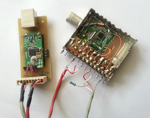
From a RTL2832U dongle with bad tuner to a universal board that can be used for direct HF reception or anything else when adding a tuner
The most popular RLT2832U dongles are the ones with E4000 and R820 tuners. This is due to the high frequency range these tuners have. Elonics E4000 covers 52 to 2200 MHz with a gap at about 1100 MHz and Rafael Micro R820T covers 24 to 1766 MHz.
But there are also RTL2832U based dongles with other tuners. One example is FCI FC2580 tuner (found in Trust 16738 dongle) which is capable of receiving 146 - 308 MHz and 438 - 924 MHz, limiting its use to DVB-T only! It can't even receive FM radio 88 – 108 MHz.
If you’re having such a dongle don’t throw it away. There are situations when you don’t need a tuner at all (the direct sampling mode of RTL SDR that allows direct reception of signals on frequencies lower than 28 MHz). There is also the possibility of changing the existent tuner with, for example, a satellite receiver tuner that will receive 950 to 2150 MHz.
So, I wanted a universal RTL2832U breakout board that I could easily connect to with different tuners. This is how the USB dongle board looked like.

RTL2832U dongle
I started by tracing important signals. The red line is 3.3 V power from a voltage regulator. The magenta dots on RTL2832U pins are GPIOs. The yellow and light blue traces are I2C bus lines. I and Q lines are passing through coupling capacitors C24 - C27.
The thick blue line is where I intend to cut the board! This is the result of cutting the board.

RTL2832U dongle - cut board
This was just a test to see if the RTL2832U is still working. And it is. The next step was to attach this board to a larger PCB with pinheaders and USB connector. This is the result.

RTL2832U universal board
The board was made on-the-fly without a prior design. I used a screwdriver to scratch some traces. The board contains an 8 pin header for I2C bus, I/Q inputs and 3.3 V output. The 3 pin header contains GND and two AGC signals (wires soldered directly to RTL2832U pins). The unpopulated holes in the PCB are for a GPIO header that I didn’t connect (yet) due to soldering difficulties.
If you look carefully at the dongle board, at the place of the old USB connector, you will see there is nothing connected to the 5V power line. This is because I removed the original 5V to 3.3 V switching regulator from the bottom of the board and I supply the RTL2832U with 3.3V from a linear 1117 regulator located on the bottom of my homemade board. Wires are below, passing through the sponge between RTL2832U board and my board. I2C bus lines come also from the bottom side (the two black wires).
Direct sampling
Now, this thing can be used just as it is by connecting an antenna to I input and using RTL2832U in direct sampling mode. You should use a balun to adapt 75 ohms unbalanced antenna to higher impedance balanced input of RTL2832U. I used with success a home made toroid transformer. The primary side should be 3 to 10 turns. The secondary winding should be double of turns with a center tap. The center tap connects to GND! You can use some series resistors for better impedance matching.

RTL2832U impedance adapter for direct sampling
It is also recommended to use a lowpass filter to remove unwanted interferences from VHF band.
Using a tuner
There is also the possibility of adding a tuner. This requires some programming knowledge because SDR tools will not know how to control the tuner (unless it is E4000, R820, R828, FC0012 or FC0013). I’ve made tests with the MxL5007T tuner (the modified librtlsdr can be found on GitHub).

RTL2832U with MxL5007T tuner
I didn’t connect MxL5007T AGC pin to RTL2832U AGC because I measured 0 volts on both AGC outputs of RTL2832U (I don’t know whether there was not sufficient input signal or my soldering is the problem). I choose to set MxL5007T to maximum gain using a 100 ohm resistor connected from 3.3 V to AGC.


No comments :
Post a Comment
Please read the comments policy before publishing your comment.